The Print command (File>Print) is used to print all or a portion of the layout.

The Print Setup command (File>Print Setup) is used to set up the printer properties.
When the Print command is selected a grid, which represents each printed page, is drawn on the layout. Pages can be selected or unselected for printing by placing the mouse over a grid section and clicking the left mouse button.
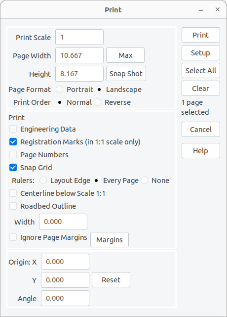
The Print dialog contains a number of control areas:
- The size of each page is controlled by:
- Scale - up to 1:1.
- Width, Height - scaled size of each page. Values for Width and Height can be manually entered, overriding the maximum values. Values larger than the page size times the Scale cannot be entered.
- Max - sets Width and Height to the maximum for the print Scale.
- Snap Shot - adjusts the Scale, Origin and Angle to produce a one-page snap shot of the layout.
- Format - Portrait or Landscape.
- Page printing order is controlled by the Print Order option.
- Relative to the Print Grid:
- Normal order is Columns first, Top to Bottom, Left to Right.
- Reverse order is Rows first, Left to Right, Bottom to Top.
Whether tracks are printed with one or two lines (representing the center line and rails) depends on the Print Scale. If this value is smaller than or equal to twice the Two Rail Scale on the Display (Display Dialog) dialog then tracks are drawn with two lines. This corresponds to the way tracks are drawn on the main window, adjusted to account for the greater resolution of most printers. At 1:1 tracks are also drawn with a center line.
- Other options:
- Engineering Data - show title, user, date and other information in a box at the bottom of the printout.
- Registration Marks - at 1:1 scale, print location markers every 3" (or 10cm). This option is only enabled at 1:1. This is useful for aligning multiple pages printed at different angles.
- Page Numbers - to help positioning the individual pages the page number is printed in the center of the page in the format (x/y). x is the page position from left to right, y in from bottom to top, So (1/1) is the page at the bottom left. As an additional aid, the numbers of the next pages are printed on each edge.
- Snap Grid - if the Snap Grid (Grid Dialog) is visible then it may be drawn on the printout. This option is only enabled if the Snap Grid is visible.
- Rulers - choose to print rulers at the layout edge, or on all edges of the page, an option is only enabled if the Angle is 0.000, or None - which means print no rulers.
- Centerline below Scale 1:1 - dotted line down the center of the Track/Roadbed. This line will always be printed at Scale 1:1, but selecting this option will print it at smaller scales. This option is disabled if tracks would be drawn with only one line (instead of two).
- Roadbed Outline - lines representing the edge of the Roadbed. The Roadbed will be printed if the Width is greater than the track gauge. Note: this option is most useful at 1:1. This option is disabled if tracks would be drawn with only one line (instead of two).
- Ignore Page Margins - use the physical page size. This allows the printouts to abut without trimming.
- Margins - examine and update the printer margins for the current printer. (Printer Margin)
- The orientation of the print grid is controlled by:
- X - X co-ordinate.
- Y - Y co-ordinate.
- Angle - of the grid.
These values can be set directly or by dragging on the layout. Shift+Left+Drag moves the grid and Shift+Right+Drag rotates the grid. The Reset button resets the values to 0.
The Print button prints the selected pages and closes the Print dialog. It is not enabled until you have selected some pages to print.
The Setup button invokes the Printer Setup (Printer Setup) dialog.
The Select All button selects all pages for printing.
The Clear button unselects all selected pages, so no pages will be printed.
The Filter Layers/Groups... button opens the Filter Layers/Groups for Print/Export dialog (Filter Layers/Groups for Print/Export) to further scope what's printed to specific Layers or Layer Groups (Layer Groups Dialog), on top of whatever Layer visibility already allows through.
Suggested Uses:
Use the Snapshot button to set the scale and orientation for a one-page printout of the layout. Also set Engineering Data to add the Layout Title, Scale and other data for a summary.
Use Layers (Layers Dialog) to control which tracks are visible (and printed), or use the Filter Layers/Groups... button (Filter Layers/Groups for Print/Export) for a one-off scope without changing any layer's actual visibility. Put bench-work, scenery or different tracks levels in separate layers and hide the layers you are not working with.
To transfer the drawing to the layout without printing at 1:1, make the Snap Grid (Grid Dialog) visible and orient it to match your room or layout table.
Check the Print Snap Grid toggle and use the printed grid to transfer measurements to your layout space. You may want to change the color (Colors Dialog) of the Snap Grid to make it more visible on the printout.
When you print multiple pages you can check Ignore Page Margins so pages can be placed next to each other. The tracks will line up correctly without trimming or overlapping the pages. Note: depending on your printer there will be an unprintable margin around the edge of the page.
If you print at 1:1 for direct transfer to the sub-roadbed, check Print Roadbed Outline and set Width to show lines for making cuts.
If you make printouts in strips at different angles at 1:1 (to follow tracks around a curve), check Print Registration Marks to be able to align the separate strips.